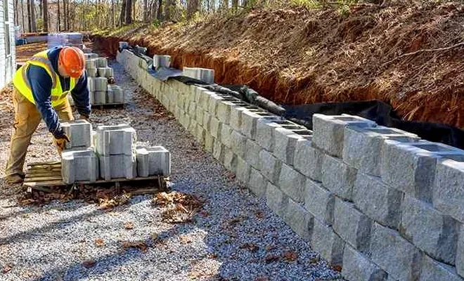
A common scenario in Sioux Falls involves a contractor breaking ground on a commercial lot near the Big Sioux River only to find the soil profile shifting from stiff glacial till to saturated sand lenses within the same excavation. It is a condition we see repeatedly across Minnehaha County, where the cut-and-fill topography of the Coteau des Prairies creates complex lateral earth pressures that standard gravity blocks simply cannot handle. Before a single yard of concrete is placed, understanding the interaction between the wall and the local geology determines whether a structure will stand for five decades or five years. We approach retaining wall design by analyzing the retained material from the bottom up, correlating the undrained shear strength with the seasonal saturation levels that characterize the 26-inch average annual precipitation in the region, ensuring the wall’s heel and toe resist both sliding and overturning from the first freeze-thaw cycle onward.
A retaining wall in eastern South Dakota must be designed not just for the soil you see, but for the saturated, frozen, and surcharged conditions that will test it every year.
How we work
Local ground factors
The IBC’s mandate for retaining wall design in Sioux Falls carries specific gravity here because of the expansive nature of the glacial till found throughout Lincoln County. When these overconsolidated clays take on water, the swelling pressure against the back of a wall can exceed the at-rest pressure by a factor of two, a condition often underestimated in preliminary design. Under ASCE 7, the wall must be evaluated for the Seismic Design Category assigned to the site, which in South Dakota typically requires at least a pseudo-static analysis for walls supporting critical infrastructure or exceeding 12 feet in height. The most preventable failure we encounter is a wall built without proper heel reinforcement, where the moment arm fails to offset the thrust from a saturated slope. Integrating slope stability analysis early in the design phase identifies the global failure surface that might bypass the wall entirely, an outcome that renders even a well-constructed stem completely ineffective. Given the rapid spring thaw that sends torrents of water through the Sioux Falls drainage basin, the drainage system behind the wall must be treated as a primary structural element, not an afterthought.
Relevant standards
ASCE 7-22: Minimum Design Loads and Associated Criteria for Buildings and Other Structures, IBC 2024: International Building Code, Chapter 18 – Soils and Foundations, ASTM D1586: Standard Test Method for Standard Penetration Test (SPT) and Split-Barrel Sampling of Soils, ASTM D2487: Standard Practice for Classification of Soils for Engineering Purposes (Unified Soil Classification System), AASHTO LRFD Bridge Design Specifications, Section 11
Other technical services
Geotechnical Exploration & Parameter Selection
A targeted drilling program using SPT and Shelby tube sampling to establish the soil strength envelope. We define the drained and undrained shear strength, unit weight, and interface friction angle for the foundation and retained soils, providing the input parameters essential for wall stem and footing design.
Structural Wall Analysis & Global Stability
Computation of active, passive, and at-rest earth pressures using both classical methods and finite element analysis for complex geometries. The model incorporates surcharge loads from adjacent structures and traffic, along with a global stability check using limit equilibrium software to confirm the wall will not be undermined by a deep-seated slope failure.
Drainage Design & Construction Specifications
Design of the wall drainage system including granular chimney drains, perforated collection pipes, and weep hole spacing to eliminate hydrostatic buildup. We produce a complete set of stamped construction drawings and technical specifications that reference ASTM material standards for backfill, concrete, and reinforcement.
Typical parameters
Common questions
What is the typical cost range for retaining wall design in Sioux Falls?
For a standalone retaining wall project in Sioux Falls, the design fee—covering geotechnical investigation, engineering calculations, and stamped construction drawings—ranges from approximately US$1,040 for a small gravity wall to US$4,500 for a large cantilever or MSE wall with complex surcharge conditions. The final figure depends on wall height, required exploration depth, and the number of global stability sections needed for permit approval.
At what height does the IBC require an engineered retaining wall in South Dakota?
The International Building Code requires that any retaining wall exceeding 4 feet in height measured from the bottom of the footing to the top of the wall be designed by a licensed professional engineer. In Sioux Falls, walls supporting surcharge loads—such as parking lots, building foundations, or roadway traffic—require an engineered design regardless of height, as do walls with slopes steeper than 2:1 above or below the wall.
How does the Big Sioux River affect retaining wall design on adjacent properties?
Properties near the Big Sioux River present three compounding design challenges: a shallow groundwater table that fluctuates seasonally, the potential for scour at the wall toe during flood events, and the presence of loose alluvial sands that can liquefy under seismic loading. Our design approach includes a scour analysis based on FEMA floodplain data, a drainage system sized for saturated flow conditions, and a bearing capacity check that accounts for the buoyant unit weight of the soil below the water table.